O-RAN Deployment Scenarios
Introduction
Deployment scenarios that the O-RAN ALLIANCE specifies, define how to compose the elements of O-RAN architecture (O-RU, O-DU, O-CU, Near-RT RIC) in the actual network deployment within the cloud and physical locations. Those are defined in O-RAN Work Group 6 (WG6).
One of the key aspects from the deployment perspective is the Open Fronthaul (O-FH), where there’s the split between Virtual Network Functions (VNFs) deployed at O-Cloud (e.g., virtualized O-CU/O-DU), and the Physical Network Function (PNF, e.g., O-RU/RRH). O-Cloud is a cloud computing platform comprising physical infrastructure nodes to host O-RAN functions, like Near RT-RIC, O-DU, etc.; supporting software components (e.g., Operating System, Virtual Machine monitoring, container runtime), management, and orchestration functions.
In this blog post, we provide an overview of different scenarios and deployment options for O-RAN functions and the related implications, like processing and transmission latency and applicable use cases.
Note: If you are interested in the Open RAN concept, check this post. If you are interested in the details of O-RAN (including all the abbreviations, like O-CU, O-DU, O-RU, etc.), here is the relevant post.
Points of Presence (PoP) and Latency
Fig. 1 shows an example, of hierarchical infrastructure with cloud computing resources at various locations along with cell sites. The Regional Cloud is placed at a central location, typically in a regional Data Center (DC) for an operator with a large computing capacity. Edge Cloud is located close to the network edge, to assure cloud computing resources at a low distant place to decrease latency for data processing. The Cell Site is a location where the radio transmission is conducted to provide coverage for the desired area.
The typical distances (see e.g., Edge Cloud (OpenNFV), or Edge Computing Group/Edge Reference Architectures (OpenStack), and specifically for O-RAN as provided in [1]) between the elements provided in Fig. 1 are:
- < 20 km, between the Cell Site and the closest Edge Cloud
- <200 km, between the Regional Cloud and the closest Edge Cloud

Taking into account the above, we will now discuss the deployment of the O-RAN Base Station (BS) components, namely O-CU, O-DU, O-RU, and Near-RT RIC. (Note, the details about the mentioned components and the logical architecture can be found in this post.)
For the BS, where we put all the entities at the cell site (i.e., O-CU, O-DU, O-RU, Near-RT RIC), we achieve the lowest possible latency for processing, and the services (e.g., video) are, most likely, processed at the edge. However, this deployment is the most expensive one – every Cell Site requires that all the functionality of the Base Station is placed there.
When we move the control of the BS (i.e., Near-RT RIC) and the connection anchor (i.e., O-CU-CP) towards the edge cloud, i.e., a more centralized PoP, we can gather/collectively manage the resources from the connected cell sites. Here, we still want to process the data including the User Plane traffic at the cell sites, thus they are kept there to ensure low latency.
Furthermore, we only leave the O-RU at the cell site by bringing other parts of the processing, including O-CU-UP and O-DU to the edge cloud. This increases the latency for data processing, while still keeping a reasonable value (e.g., 5 ms), but implements a cheaper deployment with less processing power needed at each cell site location. For the non-latency-critical services, we can bring the Near-RT RIC and O-CU even more centrally, i.e., to the regional cloud. In such cases, the latency increases to ~50 ms. This gives the possibility to have a single Near-RT RIC and resource optimization gathering processing from more cell sites while only keeping the necessary processing units closer to the user.
One of the most important topic related to where to place the particular function of a Base Station is the required latency. As we may have different services with various latency requirements, the Base Station elements may be implemented using different deployment options to realize those. For instance:
- for eMBB/mMTC services, without the very tight latency requirement, the deployment may be more centralized, with O-CU deployed in the regional cloud, and O-DU deployed in the edge cloud;
- for the URLLC type of service, the O-CU shall be deployed closer to the user, which requires realizing it along with O-DU in the edge cloud.
Note: Those requirements, when taken jointly, may be fulfilled utilizing the network slicing concept (see the accompanying blog post here), where on a single physical network, the logical functions can be deployed on different PoPs per dedicated service.
O-RAN Cloud Deployment Scenarios
Fig. 2 below shows the considered deployment scenarios as provided in O-RAN ALLIANCE documents [1].
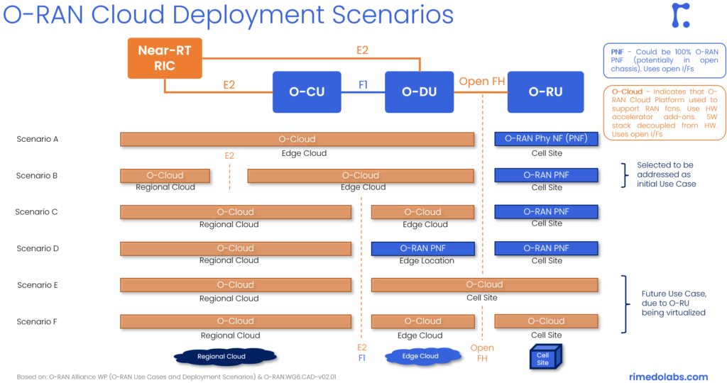
In scenario A, the whole BS is deployed at the edge as VNFs in the O-Cloud, while O-RUs are distributed to cell sites as PNFs. This minimizes the delay, but the cost of such deployment can be the largest compared to other scenarios below.
In scenario B, the actual processing of the BS (i.e., O-CU and O-DU) is deployed at the edge, so we keep low latency, but the Near-RT RIC is put centrally to the regional cloud DC to capture a broader view of the network. This is the initial use case as selected by the O-RAN ALLIANCE.
In scenario C, only the O-DU is at the edge, while we move O-CU to the regional DC to save cost and decrease energy consumption at the edge location. O-CU, in general, is working on a similar time scale as Near-RT RIC and thus they can be put together. Only the O-FH has stringent latency requirements, while E2/F1 interfaces can be more relaxed.
In scenario D, the setup is as in scenario C, but the O-DU is realized as a physical network function/device. This option enables the use of high-performing and optimized hardware for MAC/high-PHY layer processing.
In scenario E, everything is virtualized – down to O-RU (which, of course, can use hardware accelerators). In such a case, we put O-DU together with O-RU at the cell site with the high-performing CoTS hardware for PHY layer processing. This is considered for future use as the virtualized versions of the low-PHY layer and other O-RU aspects are not yet there.
Finally, in scenario F, all elements are also virtualized (as in scenario E), but with different locations for O-RU and O-DU. This scenario is also (as scenario E) considered for future use for a similar reason.
Example Mapping of O-RAN Functions to Cell, Edge, Cloud
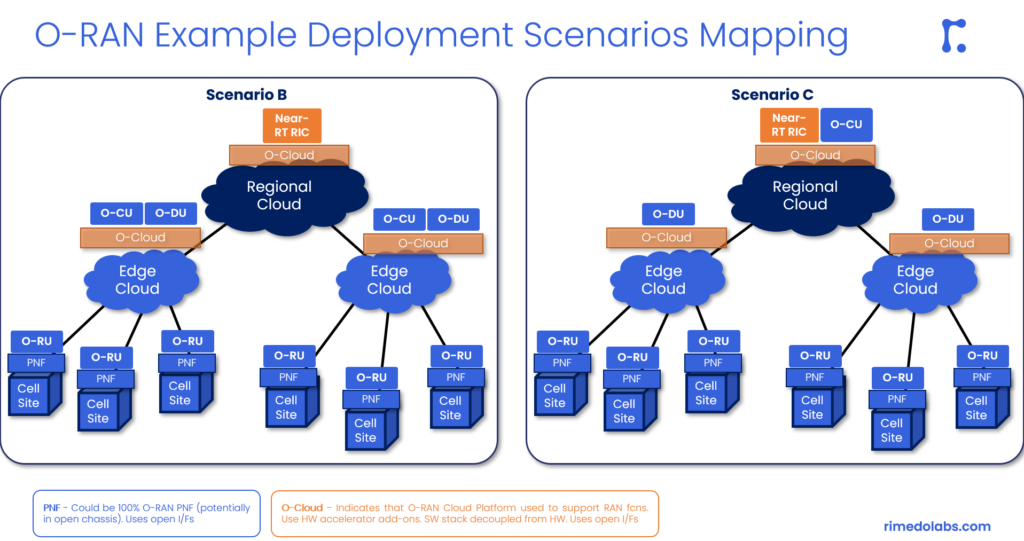
The below figure (Fig. 3) shows an example mapping of O-RAN functions to PoPs towards the O-RAN architecture within the selected deployment options.
The left part of Fig. 3 shows the actual deployment of Scenario B, i.e. Near-RT RIC is placed in the regional cloud, while the virtual O-CUs and O-DU are at the edge cloud and O-RU sits at the cell site. This is suitable, e.g., for outdoor deployment in an urban scenario for low latency applications. As a rule of thumb, 1 O-DU can be connected to tens of O-RUs (see, e.g., [1]) to achieve pooling gains (or statistical multiplexing).
On the right-hand side of Fig. 3, we have scenario C, where, compared to scenario B, the O-DU stays at the edge, while O-CU is moved more centrally to a regional cloud. This is suitable e.g., for urban scenarios with eMBB/mMTC applications. Such deployment allows the saving of computing power and energy consumption at the edge locations. This is, because 1 O-CU may handle up to tens of O-DUs, while each O-DU can connect to tens of O-RUs (see, e.g., [1]).
Summary
To summarize, the presented different deployment scenarios vary in the following terms:
- which elements/RAN functions are virtualized (realized as VNF and deployed on O-Cloud) and which are realized as physical devices (PNFs),
- how are the entities distributed among different PoPs. The processing is either distributed to remote locations for latency purposes or centralized, to achieve pooling gains and energy savings.
Depending on the scenario, use case, services, and application requirements that are there in the network, the configuration and deployment may be different. For example, for mMTC type of services, the centralized option is feasible, while for the low-latency cases or private networking, localized deployment is required (see more elaboration on this aspect in the following post).
It is important that there is this flexibility provided by the O-RAN ALLIANCE specifications, which enables those different options to realize various use cases and fulfilling varying application requirements.
References
[1] O-RAN.WG6.CADS-v04.00, „Cloud Architecture and Deployment Scenarios for O-RAN Virtualized RAN”, O-RAN ALLIANCE, WG6, Technical Report, 10.2022
[2] „O-RAN Use Cases and Deployment Scenarios”, O-RAN ALLIANCE, Whitepaper, 02.2020
Rimedo Resources
- Other O-RAN posts: Introduction to O-RAN: Concept and Entities, O-RAN Architecture, Nodes, and Interfaces, O-RAN Near-Real-Time RIC, O-RAN Use Cases: Traffic Steering
- O-RAN whitepapers: The O-RAN Whitepaper 2022 (RAN Intelligent Controller), The O-RAN Whitepaper 2021
- O-RAN products and services: O-RAN – RIMEDO Labs
- O-RAN slicing webinar Network Slicing in O-RAN (intelefy.com)
- O-RAN course O-RAN System Training (intelefy.com)
Author Bio
Marcin Dryjanski received his Ph.D. (with distinction) from the Poznan University of Technology in September 2019. Over the past 12 years, Marcin served as an R&D engineer and consultant, technical trainer, technical leader, advisor, and board member. Marcin has been involved in 5G design since 2012 when he was a work-package leader in the FP7 5GNOW project. Since 2018, he is a Senior IEEE Member. He is a co-author of many articles on 5G and LTE-Advanced Pro and a co-author of the book „From LTE to LTE-Advanced Pro and 5G” (M. Rahnema, M. Dryjanski, Artech House 2017). From October 2014 to October 2017, he was an external advisor at Huawei Technologies Sweden AB, working on algorithms and architecture of the RAN network for LTE-Advanced Pro and 5G systems. Marcin is a co-founder of Grandmetric, where he served as a board member and wireless architect between 2015 and 2020. Currently, he serves as CEO and principal consultant at Rimedo Labs.
Good one!
Very good and clear article! Thanks!
BR, Aleksei