O-RAN Architecture, Nodes, and Interfaces
In the previous post, Introduction to O-RAN: Concept and Entities, we’ve looked at the overall O-RAN concept as provided by O-RAN Alliance [1]. This time, we’re going to discuss the different nodes and interfaces creating the flexible and disaggregated O-RAN architecture along with various options for implementation.
O-RAN Nodes
Fig. 1 shows a high-level view of the O-RAN Alliance’s defined nodes. The blue elements are 3GPP defined and adapted by O-RAN specifications (thus the „O-” is added), while the orange ones are O-RAN defined elements. (Note: the interfaces between the elements are explicitly not shown in this figure – they are introduced in the next section of this post.)
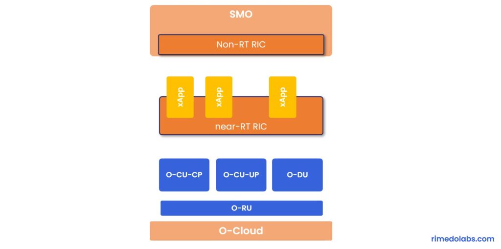
The individual elements are the following:
- O-Cloud: a Cloud Computing platform comprising physical infrastructure nodes to host O-RAN functions, like near RT-RIC, O-DU, etc.; supporting software components (e.g. OS, VM monitoring, container runtime), management, and orchestration functions.
- O-RU (O-RAN Radio Unit): a logical node hosting a low-PHY layer (e.g. FFT/IFFT, PRACH) and RF-based on LLS (Lower-Layer Split);
- O-DU (O-RAN Distributed Unit): a logical node hosting RLC (Radio Link Control) / MAC (Medium Access Control) / high-PHY layers based on LLS;
- O-CU-CP (O-RAN Central Unit-Control Plane): a logical node hosting RRC (Radio Resource Control) and CP (Control Plane) part of PDCP (Packet Data Convergence Protocol);
- O-CU-UP (O-RAN Central Unit-User Plane): a logical node hosting SDAP (Service Data Adaptation Protocol) and UP (User Plane) part of PDCP;
- near-RT RIC (near Real-Time RAN Intelligent Controller or nRT RIC): a logical node enabling near-RT control/optimization of RAN elements and resources via fine-grained data collection and actions over E2. nRT RIC may include AI/ML workflow.
- Non-RT RIC (Non-Real-Time RAN Intelligent Controller or NRT RIC): a logical node enabling Non-RT control/optimization of RAN elements and resources, capturing AI/ML workflow, and policy-based guidance of applications/features in nRT RIC;
- xApp: an application designed to run on nRT RIC, likely to consist of one or more microservices, that identifies data to consume and provide. xApp is independent of nRT RIC and may be provided by a third party.
- SMO (Service and Management Orchestration): a system supporting orchestration of O-RAN components that includes NRT RIC.
The different building blocks could in general be provided by separate vendors, thus can create an ecosystem of players developing only CUs, or DUs, or only xApps or RICs etc. This is where the advantage of the O-RAN concept sits.
O-RAN Architecture
Let’s now take a look at the overall O-RAN architecture (Fig. 2), where the entities provided in Fig. 1 are connected by the interfaces as per O-RAN Alliance specification [2].

As before, the „blue” entities are specified by the 3GPP (both including functionality provided by blue boxes as well as interfaces, like F1 and E1), while „orange” elements and interfaces are specified by O-RAN Alliance. Let’s now focus on the „orange” interfaces:
- A1 interface is defined between NRT RIC and nRT RIC, through which NRT RIC provides nRT RIC with policies, enrichment info, and ML model updates, while from the other hand, nRT RIC provides back the policy feedback (i.e. how the policy set by NRT RIC works)
- E2 interface actually touches and gets into the specific entities within the base station, i.e. O-RU, O-DU, O-CU. Therefore, e.g. from one side we can control what is happening within that BS, using monitor, suspend, override, control messages, and execute actions coming from by xApps/nRT RIC, and gets data collection and feedback from those entities.
- O1 and Open-Fronthaul M-plane interfaces – a regular FCAPS (Fault, Configuration, Accounting, Performance, Security) interface with configuration, reconfiguration, registration, security, performance, monitoring aspects exchange with individual nodes, like O-CU-UP, O-CU-CP, O-DU, O-RU, as well as nRT RIC.
- O2 interface – to manage the platform resources and workload (like resource scaling and FCAPS).
The figure also shows the three control loops, namely the first control loop being real-time, where actions of a timescale below 10 ms take place, like the scheduler being in the O-DU and that is not subject to the O-RAN Alliance specification. Then we have the near-real-time control loop, with timing between 10 ms and 1 s, where the functions like Traffic Steering, Mobility Management, and Interference Management operate. Finally, the most outer control loop touches the non-real-time operations of more than 1 s, with orchestration and optimization functions and incorporation of ML models.
O-RAN Implementation Options
Fig. 3 and Fig. 4 show various options for the implementation of O-RAN architecture based on [2]. Note, the E2 Node is a logical node terminating E2 interface, for NR it is O-CU-CP, O-CU-UP, O-DU or any combination as allowed by O-RAN Alliance.
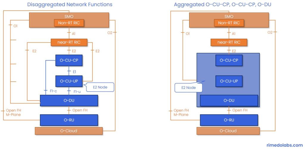
The left side of Fig. 3 shows the totally disaggregated architecture (i.e. the same that we saw in Fig. 2), where nRT RIC has E2 connections to each individual O-CUs, and O-DU which then become individual separated E2 Nodes. Then, the nodes can be aggregated in different ways. One example option is shown on the right side of Fig. 3, where O-CU and O-DU are combined together and this is then collectively treated and called as a single E2 Node, to which there is only a single E2 connection (and a single O1 connection).
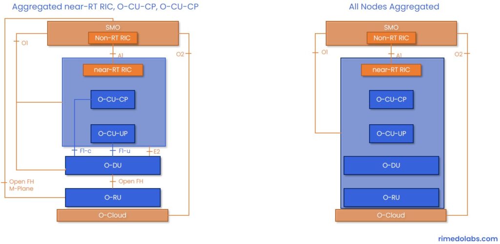
The next set of options in Fig. 4 show a different way to combine the different functional elements. The left side of that figure presents the incorporation of nRT RIC together with O-CUs, which means that the E2 interface to control O-CUs is internal, and from that combined node there is a regular E2 interface towards O-DU only. Finally, the right side of Fig. 4 presents an option where all the nodes (except SMO) are combined together, thus the E2 interface is fully internal, and there is only a single O1 connection, and the always present A1 interface.
Summary
This post discusses the nodes and interfaces defined by O-RAN Alliance. The provided implementation options visualize one of the benefits of O-RAN, namely the implementation flexibility with the open O-RAN architecture. Those options from one side provide the flexibility in implementation and various vendor configurations, but the price to pay for this variety is that you need a way to identify the internal nodes, that you want to control, i.e. it requires the E2 interface and O1 interface to be able to capture all those different options and encapsulate control elements for e.g. O-DU only.
If you want to get into more details on the near-Real-Time RIC, check out the next blog post in the series: O-RAN near-Real-Time RIC (RAN Intelligent Controller).
Note that O-RAN Alliance just recently released a new set of specifications together with significant updates to the existing ones [3].
RIMEDO Labs Resources
- The O-RAN Whitepaper: Sign up for our newsletter to download: The O-RAN Whitepaper
- Blog posts: Check out other posts post in this series: 1. Introduction to O-RAN: Concept and Entities, 3. O-RAN near-Real-Time RIC (RAN Intelligent Controller), 4. O-RAN Use Cases: Traffic Steering
- Webinar: A video recording from a webinar discussing the above aspects, and architecture, RIC internals, use cases, with a special focus on traffic steering: O-RAN Architecture and Use Cases – YouTube
- Slides: Sign up for our newsletter to get a free copy of slides on O-RAN Architecture and Use Cases
- Training: Sign up for our O-RAN System Overview Course.
- Poster (High quality, printer-friendly, A3): Subscribe to get your O-RAN Poster copy.

References
[1] O-RAN ALLIANCE (o-ran.org)
[2] O-RAN.WG1.O RAN Architecture Description v03.00, „O-RAN Architecture Description”, November 2020
[3] O-RAN ALLIANCE Introduces Minimum Viable Plan Towards Commercial O-RAN Solutions and 28 New O-RAN Specifications Released Since November 2020
Author Bio
Marcin Dryjanski received his Ph.D. (with distinction) from the Poznan University of Technology in September 2019. Over the past 12 years, Marcin served as an R&D engineer and consultant, technical trainer, technical leader, advisor, and board member. Marcin has been involved in 5G design since 2012 when he was a work-package leader in the FP7 5GNOW project. Since 2018, he is a Senior IEEE Member. He is a co-author of many articles on 5G and LTE-Advanced Pro and a co-author of the book „From LTE to LTE-Advanced Pro and 5G” (M. Rahnema, M. Dryjanski, Artech House 2017). From October 2014 to October 2017, he was an external advisor at Huawei Technologies Sweden AB, working on algorithms and architecture of the RAN network for LTE-Advanced Pro and 5G systems. Marcin is a co-founder of Grandmetric, where he served as a board member and wireless architect between 2015 and 2020. Currently, he serves as CEO and principal consultant at Rimedo Labs.